Body lift and roller plans info.

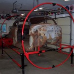
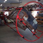
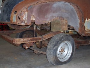
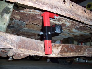
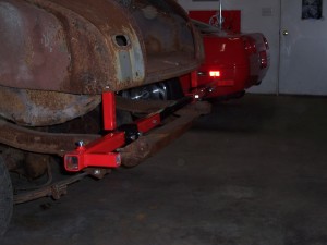
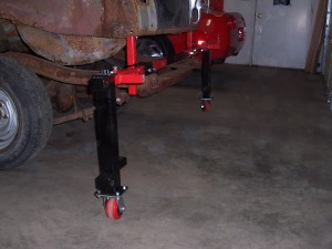
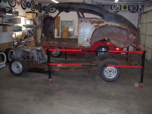
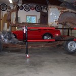
100_0739Back in 2005 my father and I came up with a body lift and roller system that would allow one person to separate a car body from it’s frame. With a standard rotisserie the biggest problem we saw was how to get the body onto the rotisserie with out having 4 guys come over to manually lift it. An even bigger problem we saw was, after you completely restored your car body (fresh paint and all) how were you going to put it back on the frame?

Here are some of the benefits:

  • Fully adjustable for any sized car including truck cabs
  • Can be used as a body cart for portability
  • Can be made to fit under an 8′ ceiling
  • Legs are telescoping for easy height adjustment
  • Universal to fit any type or model of car
  • Can be operated with minimal shop tools(9/16″, 3/4″, 11/8″ sockets)
  • Has a capacity of 1500 pounds
  • Body cart can be used with a standard auto rotisserie
  • Firewall and trunk are completely accessible
  • Breaks down for easy storage
  • Will adjust from 5′ to 8′ wide
  • Will adjust from 6′ to 12′ long
  • Will adjust from 24″ to 39″ high
  • Capable of raising bodies as low as 10″ from the ground

The body lift & roller plans are 50 pages of easy to follow blueprints that are based on common sense and not engineering jargon. There is more than enough information on the drawings to successfully build a complete body lift and roller.

The capacity drawn is for 1500 lbs. If you have the skills to restore a car, you have more than enough skill to build this body lift. Every part is clearly drawn and dimensioned in 4 views including a pictorial view for clarity. The blueprints also come with building notes and a full material and cut list.
 

Body lift and roller plans building notes.

These are the notes that come with the plans.

These building notes are put together as guidelines and are placed in no particular order of importance. I would suggest reading through them before starting the project. I would also recommend reading through the instruction manual as well. That will give you a better idea of the project and how it works as an end result.

The body lift & roller is made up of 8 different main parts and many different pieces to make up the main parts. The main part names are as follows: Legs, Main beams, Cross braces, Hoops, Hoop connectors, Hoop hook up, Body mount bracket, And Body mount. I have made drawings of all the individual parts as well as the main parts.

All nuts should be welded on at least 3 sides and that is if you are a good welder, if not they should be welded all the way around. It has been my experience that using smaller nuts not only dents the tube you are pressing against but over many uses of the rotisserie the nuts can become stripped out. Not to mention more warping during welding making them hard to use. A quick tip is after welding the nuts, run a tap through the threads after it cools down. This will make life a lot easier for using the unit in the future. Also, unless otherwise stated in the drawings, all nuts to be welded are 1/2”. Most of the parts have both through holes and pinch bolts to hold everything together. The through bolts are for safety and the pinch bolts are for taking the slop out of the mating parts. It is strongly recommended to use both.

The caster plates are a for a standard 6” caster. If you are going to use a different size I would recommend getting the caster first and making the plates to fit your casters.

The .188” thickness is a standard tube size that not only makes the body lift heavy duty but also makes all the tubes slide inside one another quite nicely. I wouldn’t use lighter tube because of strength reasons as well as the amount of slop in between mating parts.

You will notice in the prints that I call out some weird hole sizes. I drill all my holes 1/32” bigger than the bolt I use to make life easier down the road. There is nothing wrong with making the holes exact size or 1/16” bigger. It all depends on what drill bits you already have. If I call for a .813” hole and you only have a 3/4” bit by all means use it instead of going out and buying a new bit. If you have a 7/8” bit, use it, you get the idea. If I call for a through hole that means all the way through the other side of the tube.

You will notice on some of the 4 view drawings that some of the views are out of proportion  with the others. This is for clarity and to give you the biggest view possible for standard paper from your printer. Please note that drawings are not to scale, so don’t measure off the drawings. there is enough information on each part to build each part. If you have any problems figuring something out, just look at another print that has that part on it or a picture view. This body lift & roller was drawn with common sense in mind, it is not rocket science. If there is something really important I made a note of it on the drawing or building notes page, otherwise it is no big deal.

You will see on the leg internal parts drawings that I use a couple of 3/4” brass flat washers

per leg. This is to reduce friction from the nut turning against the top cap. I used to build the legs without them but I found using them really helps make lifting the unit up and down a lot easier. I would have used plastic washers but they will melt due to the heat from welding the nut on top and the steel flat washer underneath. Also it is a good idea not to sandwich all the washers too tightly against each other. Give them some clearance so everything will work smoothly after welding.

The hoops that are dimensioned on the prints will have an end result diameter of 8’4” tall. It all depends on how long the hoop sections and hoop section splice ends are. Here is the formula for figuring out what size you need with your garage ceiling clearance in mind.

Hoop section = 25” and hoop section splice end = 12.5” an end result of 8’ 4” diameter will occur.

(this is the way the prints were dimensioned)

Hoop section = 23” and hoop section splice end = 11.5” an end result of 7’ 6” diameter will occur.

Hoop section = 21” and hoop section splice end = 10.5” an end result of 7’ diameter will occur.

I hope this isn’t too confusing. The bottom line is: the smaller the hoop parts, the smaller the end diameter will be. The reason I went with 8’4” diameter for the plans is that you will never find a car too big to fit nicely in that size hoop. Conversely, I wouldn’t make my hoops any smaller than 7’ diameter or you will be pretty cramped even with the smallest cars.

You will notice on the plans for the legs I use 3/4” ACME threaded rod and nuts for the telescoping. This is a little harder to come by than regular threaded rod but I’ve tried the regular stuff and I ended up pulling my hair out trying to get it to work properly. Believe me there is a reason that machines with moving parts all use acme thread (lathes, milling machines) they can travel over and over again and the threads still work. Depending on how big of a town you live in you might have to order it. Just search for acme threaded rod on google to find a place to get it. I used to get mine from Williams Steel & Hardware in Minneapolis, MN. Most larger hardware stores will have it or at least order it for you.

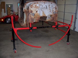
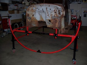
In all of my pictures you will notice that the hoops were made of pipe instead of square tubing. This is because I used to build many of these things and it was a real time saver to have pipe rolled to the diameter I wanted and just cut it into quarter sections. Because of the expense in paying someone to roll your hoops, I chose to show it in sections of square tubing that can be welded together. If you have the equipment and/or the ability to roll pipe or tube that would be just fine, but I felt that most people wouldn’t even bother. I know I wouldn’t if I was only going to build one. The only reason I went with pipe instead of square tube was that, the cheapest company to do it could only roll pipe. The concept is the same no matter what material you use.

Let’s talk a minute about the fact that I did not dimension any hoop hook up procedures. All the parts needed are dimensioned. There are way too many variables involved for me to give hard dimensions on the hoop hook up procedure. The fact that I don’t know your garage ceiling height, your car width, not to mention that if all of the hoop sections got cut even 1/4” shorter or longer will drastically change the over all dimensions, is why I did not dimension the procedure. If I did, someone would build all the parts without reading these building notes and then realize that it won’t work. It is a very simple process and it goes as follows:

Once the body lift is built and put together, raise the legs about 6” higher than their lowest position. (Make sure you have the casters installed). Also make sure the body lift is put together at least 7’ wide. (Around 7’ seems to be the best). Next, install the hoop hook up tube to the main beam short tubes sticking out. Then put the fully assembled hoop in front of the lift like the print shows on the hoop hook up instructions page (the hoop should be touching the ground). Once both sides of the hoop is touching the hoop hook up tubes you will want to tack weld them to the hoop. (Tack them in a couple spots so they won’t break off when you remove the hoop from the main beams). Once that is done you can put the hoops on a bench for welding and installing the gusset plate. You now know that once the car is on the body lift and you go to install the hoops, the legs will be able to be lowered all the way, so the hoop is on the ground, and the legs can be taken off. I hope this wasn’t too confusing. You might want to read this again due to my lack of writing ability. I won’t leave you high and dry, so here is my cell phone # Matt Kline  I hope you won’t need to call, but just in case, there it is. You can also contact me anytime from my website www.redwingsteelworks.com or .org. Another good reference for this is all the pictures on my website and the instruction manual.

Auto rotisserie plans building notes.

These are the notes that come with the plans.

I have built and used many different auto rotisseries. The exact replica of this one is among the best and cheapest to make. This is a “no frills” rotisserie, after all the trial and error building different features these seem to be the best.

The rotisserie is made up of 7 different main parts and many different pieces to make up the main parts. The main part names are as follows: End frame, Hanger bracket, Pivot point, Pivot arm, Mounting arms, Body mount bracket, And Body mount. I have made drawings of all the individual parts as well as the main parts.

All .75” nuts should be welded on at least 3 sides and that is if you are a good welder, if not they should be welded all the way around. It has been my experience that using smaller nuts not only dents the tube you are pressing against but over many uses of the rotisserie the nuts can become stripped out. Not to mention more warping during welding making them hard to use.

Many of the parts are designed with ease and usability in mind. For instance The body mounts and body mount brackets are optional. If you don’t think you need them for easy hook up for your car then don’t build them. Just drill the hole in the end of the mounting arms that I call out in the part drawings. The caster plates are obviously optional and only needed if you want to be able to move the rotisserie around. The caster plates are a for a standard 6” caster. If you are going to use a different size I would recommend getting the caster first and making the plates to fit your casters.

The gusset plates are more for added welding surface than they are for structural integrity (except for the pivot point gusset plate, it is for both reasons). If you want to make the gusset plates bigger that is fine, but I wouldn’t make them any smaller.

The space between the hanger bracket and the end frame is enough in case you wish to add a hydraulic jack to raise and lower the pivot point up and down the end frame vertical tube.

The .188” thickness is a standard tube size that not only makes the rotisserie heavy duty but also makes all the tubes slide inside one another quite nicely. I wouldn’t use lighter tube because of strength reasons as well as the amount of slop in between mating parts.

You will notice in the prints that I call out some weird hole sizes. I drill all my holes 1/32” bigger than the bolt I use to make life easier down the road. There is nothing wrong with making the holes exact size or 1/16” bigger. It all depends on what drill bits you already have. If I call for a .813” hole and you only have a 3/4” bit by all means use it instead of going out and buying a new bit. If you have a 7/8” bit, use it, you get the idea. If I call for a through hole that means all the way through the other side of the tube.

You will notice on some of the 4 view drawings that some of the views are out of proportion  with the others. This is for clarity and to give you the biggest view possible for standard paper from your printer. Please note that drawings are not to scale, so don’t measure off the drawings. there is enough information on each part to build each part. If you have any problems figuring something out, just look at another print that has that part on it or a picture view. This rotisserie was drawn with common sense in mind, it is not rocket science. If there is something really important I made a note of it on the drawing or building notes page, otherwise it is no big deal.

Body lift and roller photos

100_0717100_0722100_0769100_0770100_0750100_0726100_0720100_0739100_0766100_0724

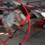
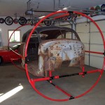
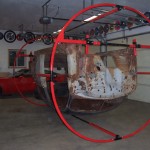
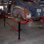
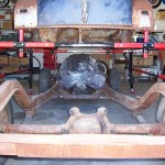
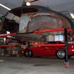
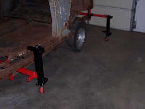
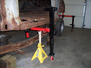
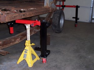
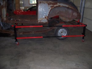
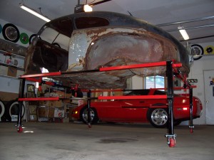
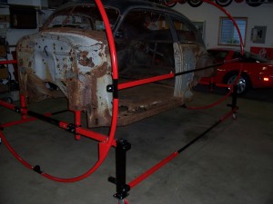
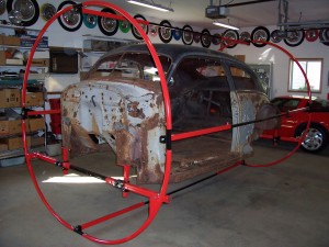
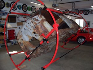
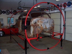
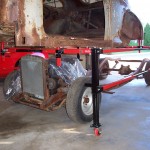
As you can see in the photos, this unit has a big advantage if you need to work on the rear or the firewall. Also note just how high the body lift actually goes. You could sit in a chair to repair body mounts. The entire unit breaks down for easy storage.

Body lift and roller step by step instructions.

Block the car up off the frame 6”.

We recommend 6” in order to have enough clearance to install the body

mounts and the main beams.

100_0654

Install the 4 body mounts along with the body mount blocks.

Make sure to use body mount locations on your car that are in good

enough shape to support the car when it is on it’s side or it’s top. If your

car’s body mounts are rusted out you will need to repair them first or find

different ones.

Also make sure that the car will not be front or back heavy when you find

a good mounting location.

The body mounts as well as the blocks are made to face any direction in

order to work around objects such as the frame.

The body mounts and blocks must hang straight down. A series of washers

or wedges may be needed for some cars in order to achieve this.

Use a 3/8” x 3” bolt, nut, and lock washer to set and secure the height of

the body mounts.

Do not tighten any bolts at this time.

100_0656

When installing the main beams, slide one half beam through the body

mount block. Then install the main beam insert from the other side of the

car. Then you can go ahead and put the second half beam through the

other body mount block.

Remember that if you are going to be using the hoops, the total width of

the main beam should be 7’ from the outside to the outside, in order to

hook up the hoops correctly.

It is best if the hoop hook up pegs stick away from the car as shown.

Be sure to have the main beam insert centered between the two main beam

halves, in other words, you want the same amount of steel inside each half

for the greatest strength.

Make sure to have the entire main beam centered side to side, inside the

body mount blocks as well.

As a reminder, everything should be hanging straight down from the body

mounts, so when the legs are attached they will be perpendicular to the

floor and won’t put undo stress on the car’s body mounts.

100_0666

Install the casters using 3/8” x 1” bolts, nuts, lock washers, and flat

washers (on the slotted holes).

In the case like this picture, the car is already high enough off the ground

to install the legs (using the top peg of the legs) into the main beams.

Make sure the legs are facing the right direction in order to receive the

stabilizer bars into the couplers on the outside of the legs. (2 of the legs

are made opposite in order to make that happen).

Use a 1/2” x 3” bolt and nut to install the legs.

Tighten all bolts, especially the pinch bolts.

100_0675

In this case the car body is too low to the ground to install the leg with the

top peg. This is when you would want to use the bottom peg.

Use a 1/2” x 3” bolt and nut as well as the pinch bolts, and tighten them.

100_0679

Once the leg is installed, you will telescope the leg all the way up.

Make sure the other end of the car is still resting on the blocks and not on

the legs.

As a reminder, make sure the car’s body mounts are in good shape and

that all the bolts are tight.

Alternate from side to side, lifting only a few inches at a time in order to

keep the car as straight as possible.

Keep 2 jack stands under the main beam at all times just in case the leg

would tip from side to side. It would also be a good idea to either block

the casters or remove them for this process.

Now you will want to put the jack stands under the main beam and retract

the leg all the way.

100_0683

Now you have the car body high enough to put the top peg of the leg into

the main beam.

Don’t forget to tighten all the bolts.

100_0689

Now before you raise the legs, you will want to install the stabilizer bars

into the couplers of the legs.

It is important that this be done before you raise or move the car body so it

won’t rely only on the body mounts to keep the legs from tipping forward

or backward.

Secure each end of the stabilizer bars with a 1/2” x 1” bolt, nut, and lock

washer.

Tighten all bolts including the pinch bolts in the middle of the bars.

100_0691

Now the legs can be telescoped up and the body moved around.

Try to raise the car as evenly as possible, by raising each leg only a few

inches at a time.

The legs were built to sustain the force of an impact wrench, so if you

have one go ahead and use it.

I’m sure you’ve figured it out, but in order to raise the leg you must turn

the nut counter clockwise.

100_0696

Now the body is completely accessible for any work that needs to be done

at this stage.

This is the end of the body lift assembly. The next steps are to install the

roller.

100_0724

Install the 4 hoops as shown, onto the pegs of the main beams.

Use 1/2” x 3” bolts and nuts.

Do not tighten bolts.

100_0731

Next you will want to install the hoop connectors as shown.

Make sure the coupler on top is facing the right direction in order to

receive the stabilizer bars.

Use 1/2” x 1” bolts, flat washers, and lock washers.

Do not tighten bolts.

100_0735

Now install the top 4 hoops along with the last hoop connectors.

Tighten all bolts including the pinch bolts on the hoop pegs.

100_0739

Take only the top 2 stabilizer bars off the legs and install them into the

hoop connectors on the side of the car.

Then tighten the bolts for the stabilizer bars you just installed.

100_0742

Now you can take the other 2 stabilizer bars off the legs and install them

into the hoop connectors.

You can now lower the legs and remove them. Do not roll the legs

without any stabilizer bars connected to them.

Now go ahead and tighten all the bolts.

100_0772

The hoop connectors act as a natural stop to keep the car from rolling. If

you want the car at a different angle it might be a good idea to block the

roller with a 2×4 or something else. As you can see in the picture that

works pretty good.

Now you’re finished with the installation. To take it apart, obviously do all

the steps in reverse.

100_0769